Sci-tech Case Study #3: TKTS Booth


1
Figure 1 Killory, Christine, and René Davids. “TKTS Booth New York New York. “Details, Technology, and Form. N.p.: n.p., n.d. 154. Print.


This brief analysis summarizes the structural, construction, and environmental systems employed in the design of TKTS Booth located in Times Square, New York City, NY. The analysis will pay particular attention to the structural integrity and innovative design made possible with the latest advances in glass technology.

Project Description

3Architect, site, and concept

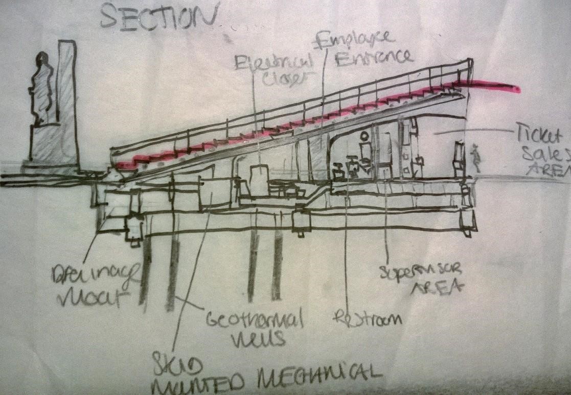
Opened in 2008, the TKTs ticket booth is essentially a series of red resin steps rising from ground level atop a steel frame. The steps function to form both a roof for TKTS’s operations as well as a grandstand for people to sit within Times Square. This sophisticated glass structure was based on a competition-winning concept by the Australian architects John Choi and Tai Ropiha while the overall structure was designed by Perkins Eastman Architects. Dewhurst Macfarlane & Partners also collaborated as the structural engineers.

The original competition simply asked for a small scale structure to replace the existing 1970’s ticket booth located within the middle of Father Duffy Square on Broadway and 47th Street. Choi Ropiha went a step further in their solution and presented a scheme that acknowledged the spatial character of Times Square being one of the world’s great gathering places.  Their proposal to create a grandstand was rooted in the notion of urban theater and was intended to enhance the Times Square experience by allowing visitors to stop and observe the continuous on-goings.

Structure

Glass is the primary material used in this structure while steel is a secondary material. Interestingly, all the glass components that are in this project are comparably stronger than their steel counterparts. Also, the structural loading calculations were cased on potential activities resulting in crowd behavior (sitting dancing jumping). Essentially, the structure can withstand twice its loading occupancy.

Essentially the structure is made up of three parts:
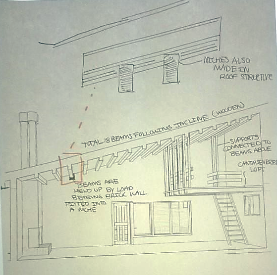
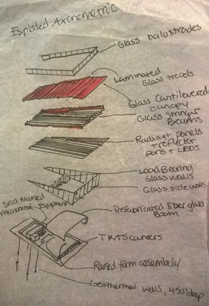
5Beams

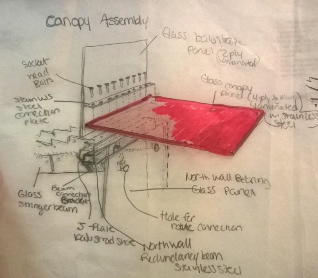
Twenty five, 30 foot long laminated glass stringer beams support red tinted glass treads between load bearing walls. The beams are made from six layers of glass; laminated in pairs, and then spliced together on staggered lengths. They are also heat-strengthened to increase strength and durability and are connected with metal bolts to the walls. These beams were held to a 2-mm tolerance over the course of the entire span.

The outermost stringer beams are attached to the perimeter glass panels with pins, and the beams connect at the top of the staircase to load-bearing glass walls at the ticket window and at the midpoint with bracketed joints—the stainless steel plate and hardware of which constitute the majority of the metal in the assembly.

Treads

There are a total of 27 steps supported by a central saw-toothed section. These treads have been heat strengthened and have a non-slip surface made from ceramic frit that has been bonded by heat through a silk screen process. The steps terminate in a large cantilevered canopy that protects the ticket buyers. LED lights, housed below the treads and accessed via the risers, illuminate the structure.

Load-bearing Walls

The glass bearing are constructed of 2″ inch thick glass panels. These walls help support the weight of the treads and at maximum measure 7-feet-wide and 17-feet-tall.  At the midpoint of the trusses—that weigh nearly 3,000 pounds apiece—a seven layer glass bearing wall comprised of four 1/2-inch-thick laminations of tempered low-iron glass and three layers of red PVB interlays. This wall alone carries approximately half of the structures weight.

Cantilevered Canopy

The load bearing walls also allow for a 6ft long cantilever to form a roof over the ticket booth patrons. This canopy, also glass, extends from the red glass treads.

Figure 2. Stringer Beam installation (top)Tread Installation (bottom)..  Killory, Christine, and René Davids. "TKTS Booth New York New York. “Details, Technology, and Form. N.p.: n.p., n.d. 161.  Print.
Figure 2. Stringer Beam installation (top)Tread Installation (bottom).. Killory, Christine, and René Davids. “TKTS Booth New York New York. “Details, Technology, and Form. N.p.: n.p., n.d. 161. Print.

Construction

The mechanical system and the body of the structure were prefabricated. Interestingly, the designers enlisted the particular help of an America’s Cup Yacht builder constructed the fiberglass shell. The reason why the majority of the parts were prefabricated was simply because of the complications that would ensure from shutting down portions of Time Square not to mention the logistics of navigating construction amidst the congestion. Prefabrication essentially, eased and expedited construction; and with the help of just one crane the structures was skid mounted, and dropped into position in a matter of hours. While this sounds fairly simple the projects timeline was actually fairly long due to the politics of the project. Simply put funding was a major issue in this project and delayed it significantly.

Environmental systems

Due to the scale of this project the environmental systems employed were few.  One defining feature is the geothermal system of five wells located 450 feet below Times Square. This system delivers a solution of water/glycol down below Broadway and back up again to heat exchangers (radiant panels) to heat and cool the space according to season. The air handling system includes high efficiency filtration to improve indoor air quality for the occupants in the ticket booth and maintain a clean interior by reducing dust accumulation on the interior surfaces.

Summary statement

The TKTS booth in New York City is a contemporary structural feat which is also aesthetically appealing. It demonstrate the capacity that structural glass has in as a building material that not only allows people to peer out to outside world from within a structure but it can also bring them to the outside world.


6 7 8 4


Resources

Killory, Christine, and René Davids. “TKTS Booth New York New York. “Details, Technology, and Form. N.p.: n.p., n.d. 152. Print.

“TKTS Booth / Perkins Eastman, Choi Ropiha.” ArchDaily. ArchDaily, 01 Dec. 2008. Web. 05 May 2015. <http://www.archdaily.com/9645/tkts-booth-perkins-eastman/&gt;.


Sci-tech Case Study #2: Alvar Aalto’s Experimental House

one
Figure 1 “Muuratsalo Experimental House (1952 -1954).” Jetsonen, Jari, and Sirkkaliisa Jetsonen. Finnish Summer Houses. New York: Princeton Architectural, 2008. N. page. Print.

This short text  summarizes the structural, construction, and environmental systems employed in the design of Alvar Aalto’s Muuratsalo Experimental House. The analysis will pay particular attention to the use of brick in the structure as well as its relation to the site relation. It will establish that the Muuratsalo Experimental House was not only a poetic expression of the architect’s interest at the time but served as a serious exploration of alternative building techniques.

Project Description

Architect, time, and objective

The Muuratsalo Experimental House was a personal summer retreat that master architect Alvar Aalto designed from 1952-54. Aalto often drew inspiration for his designs from precedents of Italian Piazzas as well as directly from the landscape. This project was no different, with the scheme being centralized around a large interior courtyard. However, the site bore a particular sentiment as it was a place that he and his new first wife had shared an attachment too. He not only wanted to create a in a place that had meaning, but just as his life was moving in a different direction he wanted to also experiment with his designs. The main experimental areas Aalto focused on in this structure was building without foundations, experimenting with free-form brick construction, free-form column structures, and solar heating.

twoSite

The Experimental House is situated across from Lake Paijanne on the western shore of the island of Muuratsalo. Measuring 53650 m2, it is a very rocky site with boulders and stones covering the landscape interspersed by bilberry, lingonberry bushes, and a birch and pine tree forest.

Major features

It consists primarily of two buildings, a large interior courtyard with a fire pit, and a number of installation walls that sprawl out into the landscape.  In addition, there’s also a woodshed, a smoke sauna, and a boat-house within the grounds. The first building (which is the primary focus of this study) contains the main living quarters as well as a lofted space that served as a gallery. The L-shape of this first building encloses the courtyard to the south and west. The second building serves as a guestroom-wing.

Structure

A foundationless foundation

The structure of Muuratsalo can be two in three parts. Starting at the ground plane, Aalto entertains the idea of a foundationless foundation. That is he doesn’t use a traditional cement foundation set in the ground but employs the natural stone found on the site to resist the gravitational forces from the load of the building.   Wanting to build without disturbing the natural landscape, he strategically places ‘free-form column structures’ (load bearing wooden footings)  and load bearing brick in the most advantageous points in the terrain to support the sub-structure of the floor. To clarify, the wooden flooring is being supported by the joists and the joists are being supported by the load bearing wall and the select wooden footings. The result is as certain parts of the terrain slope down or are absent, poche spaces are created underneath the flooring.

three

Roofing and lofted space

The load bearing brick is utilized in thick walls along the perimeter of the structure. It sits flush against the stone and adapts to terrain changes. It compressive strength and modular qualities enabled Aalto to leave voids in the wall, creating notches to house and support the wooden flooring and roof structure. In the living room of the L-shaped building, the roof is inclined and contains a lofted space. Sixteen beams support the roof. Running across the ceiling from north to south, they are slotted into the brick walls at the very incline that roofing follows. The interior of the house also has a lofted area which is cantilevered out and by wooden beams running east to west and is held in tension by supports connected to the beams that also support the roof.     

four five Construction

The experimental house was built over the course of two years utilizing brick and wood in what could be considered a passive construction method. Not only was Aalto careful not to disturb the natural landscape,  the majority of the brick used were rejects and were salvaged from another one of Aalto’s projects that was happening nearby, Säynätsalo Town Hall (1949-52). In addition, the brick was initially manufactured locally in Finland.

Essentially, the construction process was also an experimental process.  Aalto wanted to test the aesthetics of different arrangements while also monitoring how they reacted in the rough climate. Although the climatic results are inconclusive, on the walls of the internal courtyard, he was able to test different types of brick pointing, sizes, joints, and the effect of finishes on different surfaces. As a result, the walls became almost mosaic-like with approximately fifty panels of different types of brick.

Brick is noted for its compressive strength, however a large part of its strength is dependent on its bond. Therefore, it can be inferred that in Aalto’s mosaic like courtyard there are varying degrees of strength (PSI) and that the combined patterns may or may as it stable as they appear.

six seven

Environmental systems

When Aalto constructed the experimental house, the contemporary idea about sustainability was not a consideration. Rather, for Aalto it was more about building systems integration, particularly in regards to detailing and using passive systems to improve human comfort. So in addition to utilizing salvaged materials, he utilizes the courtyard as a climatic device to cool the interior of the structure.  The high walls of the structure created a microclimate by shielding the interior of the courtyard from cooling winds off the water from the north.  Ventilation and lighting was strategically allowed through the screen on the north western elevation and the entrance toward the west. Simultaneously, this allows for solar radiation to warm the space by using the solar heating properties of the brick wall and floor.eight

The solar absorptivity of a material is mostly dependent on color and density.  In the internal courtyard, the facade treatment of the house changes from white-painted plastered walls to red brick.  The white brick would reflect most of the solar radiation on the exterior while the natural brick in the courtyard would absorb it. Brick having thermal mass properties allowed it to keep the interior cool during the day while slowly releasing it after many hours at night. It is necessary, to note that structure was occupied as a summer home only because solid brick wall (no insulation) and therefore would experience heat loss in the winter months.

Summary statement

There is something to be said about revisiting not only great works but great architects but also their projects that gave birth to them. In regards to the experimental house, the use of materials in the courtyard is obviously the main focal point as the variation in pattern can only elude to the time and meticulous manipulation of the material. However, there is a much deeper environmental/comfort understanding with the implementation of these materials within a courtyard setting. Similarly, the structure of the experimental house looks as if it has a traditional frame (and in some regards it does) but on closer inspection great consideration was placed in the innovative solution for preserving the landscape. Here the architecture becomes one with it.  In all, the experimental house at Muuratsalo provides an interesting artifact of not only Aalto’s own design logic but of how innovations in building systems and technology actually come into being; through trial and error.

Resources

“Alvar Aalto, Muratsaalo Experimental House, Finland, 1952.” Atlas of Interiors. N.p., n.d. Web. 13 Apr. 2015. <http://atlasofinteriors.polimi-cooperation.org/2014/03/19/alvar-aalto-muratsaalo-experimental-house-finland1952/&gt;.

Binggeli, Corky. “Chapter 3: Stone, Masonry, and Concrete Masonry Units.”Materials for Interior Environments. Hoboken, NJ: John Wiley & Sons, 2008. N. page. Print.

Jetsonen, Jari, and Sirkkaliisa Jetsonen. “Muuratsalo Experimental House (1952 -1954).” Finnish Summer Houses. New York: Princeton Architectural, 2008. N. page. Print.

“Muuratsalo Experimental House.” Alvar Aalto MUSEUM. N.p., n.d. Web. 13 Apr. 2015. <http://www.alvaraalto.fi/experimentalhouse.htm&gt;.

Passe, Ulrike, and Francine Battaglia. Designing Spaces for Natural Ventilation: An Architect’s Guide. N.p.: n.p., n.d. Print.

Scitech: Case Study 1-Jean-Marie Tjibaou Cultural Center

Jean-Marie_Tjibaou_Cultural_Centre_mapJean-Marie Tjibaou Cultural Center

  • Located: Peninsula off of Nouméa, New Caledonia
  • Architect: Renzo Piano
  • Construction: (1991-1998)
  • Erected in honor of assassinated political leader
  • Pays homage to Kanak culture by intertwining local ancient building traditions with modern techniques


Design Process of Architect

Renzo Piano is a Pritzker Prize winning, Italian architect best known for pus­hing the li­mits of building technology and detail. While he is a proponent of using modern solutions to answer architectural problems, he does not allow this view to dictate the design. Rather for Piano, technology is a means to and end as well as something that is a part of nature.

sketch renzoPiano’s design process can be more accurately described as attempting to strike a balance between technology and creativity without following any single approach to form or theory. Working between drawing, sketch models, and the computer, he assesses the po­ten­tial of a par­ti­cu­lar si­tua­tion by being conscientious of all the specifics of a project, especially the to­po­gra­phy or urban fa­bric of the building’s site.

That is exactly what occurred in his design and execution of the Jean-Marie Tjibaou Cul­tural Centre in New Caledonia.

 Tjibaou-Cultural-Center-8Design Approach to Project

The design of the Jean-Marie Tjibaou Cul­tural Centre in New Caledonia was done under unique circumstances. Piano and his team were working under post-colonial conditions and had to be conscientious of their position as outsiders and realize whatever was created would become a symbol.

They ended up focusing heavily on the landscape and using the traditional huts of the native Kanak civilization, which comprised slender ribs of the lath structures, as a precedent. The end design was a symbolic arrangement of 10 units called “cases,” or hut pavilions. These cases were vertical tubes arranged around a central rectangular axis in three groups or village clusters with one tall hut (at 92 feet high). In contrast, the interior spaces took on a more contemporary approach with modern facilities and other accommodations.

One other concept that was at the forefront of the design was natural ventilation. In this project, simulation tools, mainly models and computer software, were used to evaluative the feasibility of the design before construction. The models were constructed so that they actually functioned like the building so that potential hurdles could be pinpointed out before construction.drawing_file_876_fr

Materials

According to Piano, the architect should understand his materials and use them to the best of their conditions.  In this case, the dearth of construction options (in regards to labor skill and material resources) pushed Piano to use a kit- of part approach. This meant that the majority of materials would be prefabricated ( in France) then brought over to the site. Piano selected glass, steel, corrugated aluminum, bamboo, and African Iroko wood as his primary materials. Iroko had a particular significance (selected for the exterior) because of its durability, connection to the natural landscape, and its ability to evoke the appearance of the traditional huts.
tumblr_ms4xxh1XYy1qln4yro1_500Structure

The walls of the cases where comprised of two concentric rings creating a double skin or a hybrid system. The interior ring/wall was composed of vertical columns of laminate iroko wood while the exterior ring/wall used curved laminated wooden members. Horizontal and diagonal steel bracing and connections were used to connect the two rings and make them rigid. This screening element is used to control the amount of heat, solar gain, and ventilation in the cases.  The roof also has a double skin system made of corrugated aluminum sheets and glass.

Use of Environmental Systems

Climate

The climate of New Caledonia is a temperate one with four distinct seasons and variations in temperatures from a winter low of 65 F to a summer high of 93 F. The average relative humidity is about 75% RH. March is when the island receives extreme weather. This includes torrential rain, winds, and even cyclones.

windsWind, orientation, and passive cooling

When there are no breezes coming off the water, the unique shape of the shell creates a Venturi Effect which pulls hot, stale air up through the space between the two shells and out of the building.To maximize cooling, the cultural center takes advantage of a passive cooling system enabled by its unique conical shape and a system of operable roof skylights, screen of laminated wood, louvres, and fixed windows. The building primarily uses two effects to push hot air out of the top: The Venturi effect and the Stack effect.

When there is a light to moderate wind (which is the majority if the time) the building uses the Stack effect. Simply by opening the series of horizontal louvres at the base of the interior façade, cool, moist air is allowed to blow in off of a nearby lagoon into the interior spaces. These louvres automatically open and close in tandem and are controlled by an integrated computer system which constantly calibrates the speed of the wind. The exterior shell wall will then work in conjunction as its orientation to the south allows the sun to beat down on it causing the air between the two layers of the double-skinned to heats up and rise out of the cavity.  For other wind conditions the unique shape of the structure in addition to the louvres system below the roof, which is fixed open, permits air pressure to balance between the interior and exterior.

drawing_file_1361_frLighting and Solar Radiation Controls

The space also uses both artificial and natural lighting. In regards to natural lighting, bamboo walls filter light into the interior spaces. On the exterior, the verticality of the cases shade the roof from the direct sun helping to control the temperature in the interior spaces. Additionally, temperature is controlled through the double roof system. The high reflectivity of aluminum screen bounces a large amount of oncoming solar radiation. Coupled with the natural ventilation occurring underneath the residual heal is driven off.

Resources

Biwole, P.H., M. Woloszyn, and C. Pompeo. “Heat Transfers in a Double Skin Roof Ventilated by Natural Convection in Summer Time.” (n.d.): 1-36. Centre De Thermique De Lyon. Web. 25 Mar. 2015. <http://arxiv.org/ftp/arxiv/papers/1312/1312.1295.pdf&gt;.

“Cultural Center Jean Marie Tjibaou.” Architecture of the World. En.wikiarquitectura, 26 Aug. 2013. Web. 20 Mar. 2015. <http://en.wikiarquitectura.com/index.php/Cultural_Center_Jean_Marie_Tjibaou&gt;.

Crawford, Scott. “An Architecture of Relationships Built on the Use of Parametric Modeling and Evaluative Analysis in Design.” Thesis. University of Washington, 2009. University of Washington Graduate School. Web. 23 Mar. 2015. <http://dmg.be.washington.edu/pdfs/MArch.Thesis.ScottCrawford.2009.pdf&gt;.

“Jean-Marie Tjibaou Cultural Center – Centre Kanak.” ArchINFORM Database. N.p., n.d. Web. 25 Mar. 2015. <http%3A%2F%2Feng.archinform.net%2Fprojekte%2F2639.htm>.

Professor, Terri Meyer Boake Associate. “Understanding the General Principles of the Double Skin Façade System.” (n.d.): 1-18. School Of Architecture, University Of Waterloo, Nov. 2003. Web. 20 Mar. 2015.

“Renzo Piano.” Encyclopedia of World Biography. 2004, “Piano, Renzo.” The Columbia Encyclopedia, 6th Ed.. 2014, and James Stevens Curl. “Renzo Piano.” Encyclopedia.com. HighBeam Research, 01 Jan. 2004. Web. 20 Mar. 2015.

“Tjibaou Cultural Center Case Study.” (n.d.): 1-8. ISites Harvard University. Web. http://isites.harvard.edu/fs/docs/icb.topic502069.files/tjibaou.pdf


Sculpture Installation: Part 2- Frolicking in Franconia, MN

WP_20140920_18_36_24_Panorama

WP_20140920_18_50_51_Panorama

In the first part of this post, I had mentioned that when I started architectural grad school my very first assignment for my studio course was to create a sculptural installation for Franconia Sculpture Park in Minnesota. Along with three of my classmates, we designed and built this piece called Apertures in 3 weeks. Three of those days were spent getting to know the artist in residence, helping out with a festival, and installing our work.  Today, I’m sharing some shots of  our stay in this whimsical place. Enjoy and visit if you have a chance because it is a really interesting place.

WP_20140920_075 WP_20140920_086 WP_20140920_101 WP_20140920_103 IMG_2366 IMG_2360 WP_20140920_053 WP_20140920_067 IMG_2433 IMG_2438 IMG_2441 IMG_2442 IMG_2460


Bonus Iron Pouring!!IMG_1212IMG_1217

Sculpture Installation: Part 1 -Projecting a new beginning

IMG_2377The beginning of my graduate program in architecture was intimidating to say the least. The very first day of our studio course my professor at the time sort of brushed over the introductions and got down the knitty gritty asking all of us about our skill sets because unbeknownst to us, we were about to embark on a pretty high level project. The initial intimidation, surely noted in our fidgeting, stemmed from two factors.

  1. We were complete strangers asked to rely on each other and navigate that weird road called a group project
  2. My program make up. One would think that a three year track composed of a small handful of people from various undergraduate backgrounds and a vast range of experiences would have some sort of advantage in bringing things to the table.  But alas our only commonality was that we all had limited construction backgrounds.

To give a little more context about the demographics of the program: There were a  total of eight of us of with 4 men and 4 women. There were two international students, 2 students with design backgrounds, one person making a career change, and the rest of us with experiences ranging from ceramics, environmentalism (me), and economics.

Nonetheless we were told that we would be embarking on a unique opportunity, one that was usually reserved for those that had to go through the bells and whistles of applications process and portfolios. That is, we would be providing two sculptural installations for Franconia Sculpture Park in Minnesota. Side note, the artist residency and internships that they offer seem like very promising experiences that I would recommend checking out if you are looking for a communal living and collectives.

Through a lot of process work and generating ideas we ended up designing a piece that was inspired by a zoopraxiscope, an early type of projector which cast images from rotating glass disks in rapid succession to give the impression of motion. We envisioned creating a giant one in which visitors could interact with and spin and change out images themselves. But due to a few factors that project became simplified and eventually we started focusing on the concept of vision restriction and framing and light. We eventually came up with this form that intermingled all three of these concepts. While its is not the most interactive sculpture, from within it, it does change the way that the park is experienced.

I’ve included some shots of our final work as well as some images from the construction and design process.


Start Date: August 2014

End Date: September 2014 

IMG_2304 IMG_2305 (1) IMG_2318 IMG_2314 IMG_2310 IMG_2328IMG_2329IMG_2422WP_20140920_140 IMG_1172 IMG_1170 IMG_0020 IMG_1167
IMG_2389 IMG_1187IMG_2390